Me too, I have troubles here. When I test it, it didn’t work. Maybe I did something wrong. I am going to try it again later.
No, you cannot. If you don’t want to use them, you can leave them alone as they are or remove the potentiometer assembly, either will have the effect of disabling the trigger. If you aren’t feeling adventurous, and don’t want to use the triggers, probably best to just leave them as they are.
If you want to use the trigger, there are quite a variety of ways you can wire it up. The ones posted in this thread will work.
did this without removing the pot and it’s giving me a diagonal down back input. do i need to remove the pots for it to work correctly?
suppose i’ll pull the pot and try it
Hi,
here is little pcb with an inverter. I call this little friend
http://1.bp.blogspot.com/_YLXgzxS8cEc/SlbPqmsayJI/AAAAAAAAAqY/YFXzaVg8J1c/s320/CIMG0798.JPG
TIM feels very well in PCB like Madcatz or Saitek 3200 and makes your triggers work  In the near future TIM gets his parts.
TIM is a very close relative to LIM.
TIM does his job with inverters.
Optocopplers can do the job, too:
http://4.bp.blogspot.com/_YLXgzxS8cEc/SlbPqXQeT9I/AAAAAAAAAqQ/pEKRwtRcXx0/s320/CIMG0799.JPG
This PCB is called SAM.
i’m having troubles with the madcatz arcade gamestick 2006 i’ve tried two methods the two resistors 20k and a diode and just 2 10 k resistors but both give me y- and z- axis signals every button works except for the triggers . oh yeah there’s one thing i desolderd both anlog sticks for saving space can this be the problem hope you guys can help me.
yep that was it i solderd it back in and it works like a charm…
hi im new here. ok i have a madkatz 360… i suppose the easier one. the one on the right
heres what i did <a href=“http://s901.photobucket.com/albums/ac211/dppham/?action=view¤t=IMG00036-20090713-1931.jpg” target="_blank"><img src=“http://i901.photobucket.com/albums/ac211/dppham/IMG00036-20090713-1931.jpg” border=“0” alt=“Photobucket”></a>
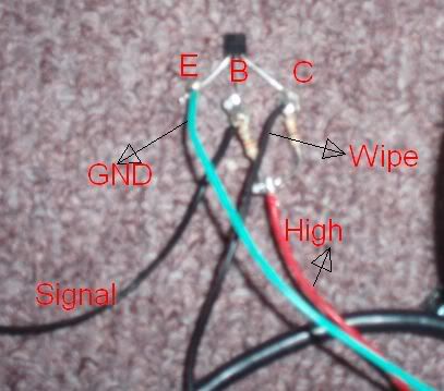
i dont know if i did it right… is it h,w,l onright trigger. left trigger is l, w, h ?

quick question:
of the different versions of the madcatz wired controller (the ones i know of are the 4716-old, 4716-new, 2008 ver), which require inversion of the signal for the triggers (ie, which require transistors for use in MC-ing)?
ive used the 2008 ver (the one that can be gotten easily from argos) a few times(ive been using pnp as they are easier for me to get but means more resistors), and i recently got my hands on an older version and i just wanted to see if i still needed transistors for it, or is it just the arcadestick madcatz that doesnt require transistors for the triggers?
Hello,
Dual mod using Madcatz 4716 (2007) and PSX pad.
(triggers hacking : 10K resistor between VCC and Wiper).
test :
on Xbox 360 : works fine !
on PS2 : problem with R2/L2 (RT/LT) :s
http://img36.imageshack.us/img36/677/sdsazze44.jpg
And no changes when pushing or releasing R2/L2.
any ideas on what is going on here ?
thanks in advance !
I’ve seen this question asked a couple of times in this thread, but I didn’t see an answer to it, so I’ll ask again and hopefully somebody can help.
(Using the 2008 model that is harder to hack)… If I don’t plan on using the triggers and I’ve already cut off the pots, what do I need to do? I’m using a dual pcb setup for this (don’t know if this is important). Do I need to do anything? Do I need to add resistors?
I wired up my 2009 madcatz controller with the 2 resistor + NPN method, and I believe I did it right. I tried getting any sort of button press out of either trigger, and the most I got was the button to register when I lifted up (boo).
Is this not the proper method? Their doesn’t seem to be a lot of info regarding these super new PCBs.
Heres my odd situation.
Im usin a rock band fender guitar and all was good till I realized the effects switch only worked when I released it with just the 10k ohm resistor.
So I figured what the hell and followed the diagram zombie had in his pic,
then windows didnt detect it, and 1+4 or 2+3 diodes would be lit up.
so when clippin the wires I realized this made it work
nothing currently connected to the PNP emitter.
5v is at the base of the 2 resistors
If I touch the wiper wire to the signal area, it goes off. and from what I can tell, only when touched, and not released.
I also found it amusing with nothing else attached at all, just touching the 5v and letting go would trigger, so I guess in a pinch I make a good ground…
Ok, reading up I see Zombies NPN was diff.
So I redid mine and still no success.
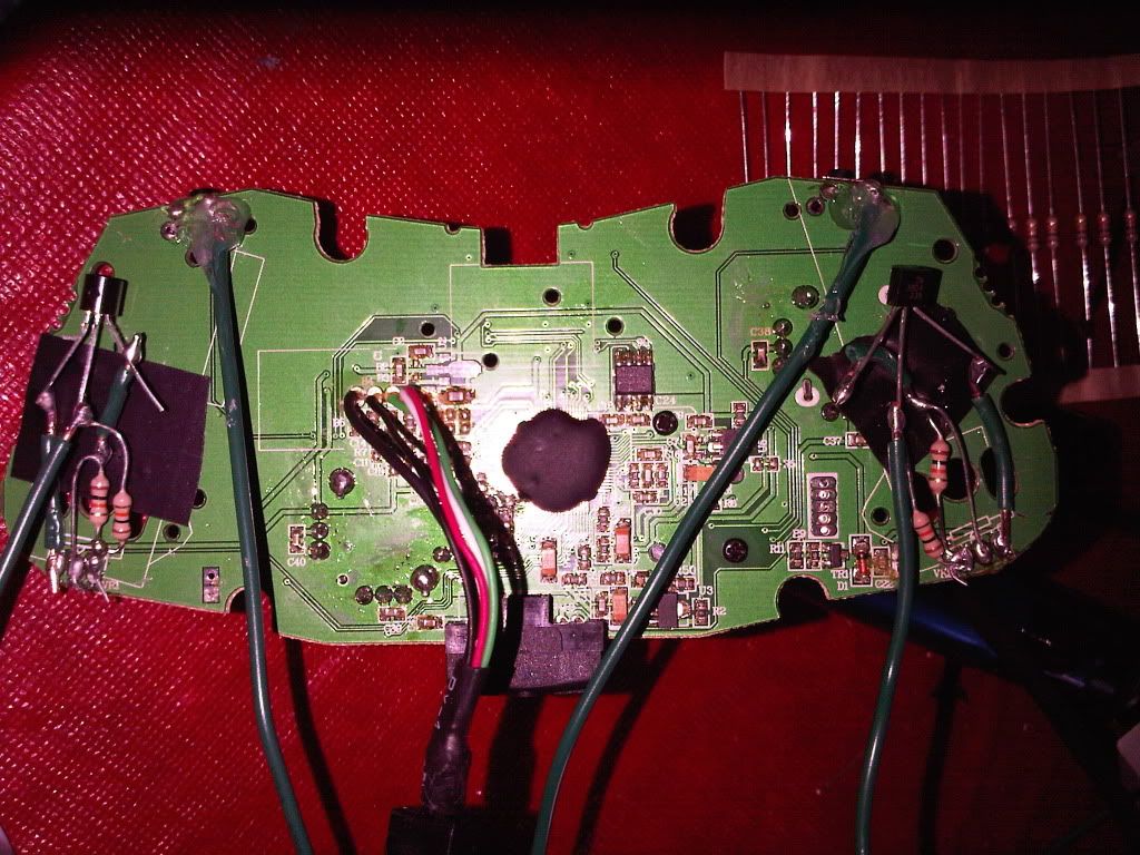
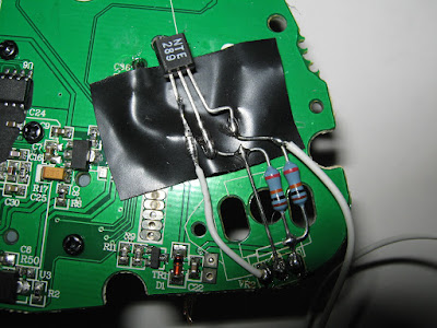
Now for pics, http://i16.photobucket.com/albums/b12/tehglow/pcb4.jpg
http://i16.photobucket.com/albums/b12/tehglow/pcb5.jpg
The radio shack package says Pin diagram when viewd from bottom
C ---- D
B ---- D
E ---- D
I reused D but you get the idea. im fairly certain I have it right, in that pcb4 pic its the flat part thats facing the camera.
Any idea whats up?
I touched other wires to the GND/Emitter area and they work. the signal line does nothing. Touched other ground to it, nothing.
If I touch the signal to the Wipe/C section it shorts and doesnt read anything till I ungplug/plug it back in.
And like mentioned earlier, when I remove all this stuff just pressing and releasing the red wire results in Zangief doing roundhouses like he should in training mode so I guess its safe to say that that is indeed the high volt wire. And since I used that ground on other signals and it works, that should be fine. leaving the wipe in the middle…
Ok, more odd stuff. In windows game controller setup, the Z axis is all the way full. If I touch that signal to the GND/Emitter, it goes down to 75%. Nothing happens in game. If I touch that signal to the High line, BEFORE the resistors, it goes to 50% and when released it will trigger the button in SF4.
Another odd thing is if I take another ground wire from the board and touch the High before the resistors, this also results in the z-axis dropping to 50% and triggering on a release…
Why would touching another GND to the high before the resistors result in the same response as the signal on the other side of the resistors touching the high?
I do believe Im way out of my scope now. the supposed 1 resistor if its usually low didnt seem to work unless im now blowing everything out of proportion.
Wow. I think I finally got it. Didnt really follow any of the stuff ive seen in this thread so far. I know this was for the madcatz but it seems the best resource for these sorts of issues.
But basically I had the GND to the Emitter. High had the 2 resistors, 1 to base, 1 to collector.
Heres the fun part. doing that has the Z axis finally to middle. Touching the Wiper to the Collector would send it back to full and trigger the button…so looks like Ill need to be wiring a “signal” to where the wiper would have gone and then wire the wiper as the ground…
Also i can switch the GND wire from emitter also to between the base and resistor and Wiper to Collector results in Z axis 75% full but triggers an attack in pc SF4 still…
Additionally it seems I can touch the Wiper to the high itself before the resistors which results in zaxis from 50 to 100. Im baffled.
Ok… this Resistor/Collector junction is working as a GND for the wipe and apparently all my other wires. Yet if I touch the wiper to any of the other grounds on the pcb, then it shorts and doesnt respond.
So it seems to me i can just wire that Collector area as my common ground, use the wiper as the signal and all is done…
scratch that. once the wiper touches that gnd it turns off every other button on it…
Toodles, does this make any sense at all?
I’m having some trouble with my triggers. I’ve done everything according to the description and the only thing i’m now not 100% on is the transistor. Can someone tell me if this npn transistor is appropriate to use.
http://pdf1.alldatasheet.com/datasheet-pdf/view/50752/FAIRCHILD/BC550C.html
Hey all, I’ve read this whole thread and I’m still not 100% on what I’ll need for my dual-pcb mod. Forgive the late post, but this thread seemed the most relevant to my questions.
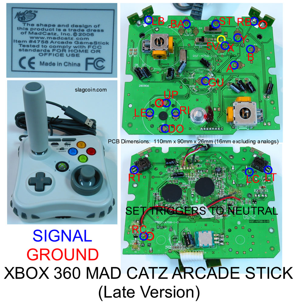
I’ve already modded a Hori Fighting Stick 3 PS3 PCB and have it working just fine (pics here: http://www.flickr.com/photos/vr/sets/72157615400468996/) on my custom Sanwa stick. Last night, I tore apart a MadCatz retro (http://slagcoin.com/joystick/pcb_diagrams/360_diagram2.jpg - model #4758) common ground PCB and wired the main 6 buttons up and it works fine so far (without the left/right triggers).
What I want to do is wire up the left and right triggers on the MadCatz retro model #4758 PCB and then do a dual-pcb mod, joining my Hori FS3 PCB with this MadCatz retro PCB. I plan on using a DPDT switch from Radio Shack and have a single USB wire coming out of the arcade stick.
From what I’ve read, I don’t need to use the hex inverters that Toodles talked about with the MadCatz retro #4758 PCB, but can just use two 10k 1/4 watt resistors (one for each trigger). Can someone please confirm that this should work not only to be able to use the triggers with my PCB, but will also work in a dual-pcb mod as I’ve described? Do I truly not need to use diodes or the hex inverter to do this dual-pcb mod?
Also, Kaoshin, did you finish your dual-pcb mod with the MadCatz retro PCB and how did it turn out? Any problems/gotchas/surprises/pics? =:)
Thanks in advance guys. You rock. =:)
Okay, so just to answer my own question (and maybe this will help someone else), I finished my dual-pcb mod today and I’m really pleased. I used a MadCatz retro model #4758 PCB for the Xbox 360 and a Hori Fighting Stick 3 PCB for the PS3. I did have to use a resistor and a diode on each trigger on the MadCatz retro, as shown here: http://img177.imageshack.us/img177/6366/1000207tg7.jpg for the dual-pcb mod. As others have stated, if you’re not doing a dual-pcb mod or if you’re not wiring to the 2 triggers, you don’t need diodes and can just use resistors. But without the diodes, what was happening was the controller worked fine on the Xbox 360, but when I plugged it into the PS3 and switched the DPDT switch to that PCB, the PS3 L2/R2 and 360 triggers were grounding out and causing problems.
Here’s a shot of [my labeled DPDT switch
http://farm3.static.flickr.com/2476/4062079268_5f65df4050_m.jpg](http://www.flickr.com/photos/vr/4062079268/),
a [close-up of the dual-pcb wiring board
http://farm3.static.flickr.com/2526/4062088192_98be1f0f45_m.jpg](http://www.flickr.com/photos/vr/4062088192/),
both [pcb’s and the inside of the box
http://farm3.static.flickr.com/2431/4062074802_ec602df425_m.jpg](http://www.flickr.com/photos/vr/4062074802/),
the finished product: http://farm3.static.flickr.com/2623/4061345557_ef2f629171_m.jpg
and some more pics.
Thanks again to Toodles and Upas who helped me last night at 2 in the morning. =:)
If anybody can help, what diode am i suppose to use if still want to dual mod my stick using the transistor method. I’m using diodes right now on my 360 PCB but ALL of the buttions and direction inputs are going crazy on the PS2 side. 360 side works fine.
I have a Madcatz Retro ArcadeStick
What I’m trying to do is set my stick up for eight buttons, was wondering what I needed to get the LT and RT to work. Do I need 2x 10k ohm Resistors and a Transistor or can I get away with the 10k resistors.