So apparently there is no chance of any Radio Shack carrying inverter chips of any kind. They told me that if it’s not on their website, it’s definitely not going to be in store. Bringing the options for finding one to: online, local specialty store, or Frys.
Guess I’ll be heading to Frys some time this weekend. 
So to clarify, the inverter is not needed if the trigger pots are left on? I’m trying to sort out an issue I’ve got now where the triggers work, unless they are pressed simultaneously. Then it reboots the pad.
In the attached pic, my obviously flawed method is the one on the right with a cherry switch, and the pot still attached the the board.
Hi,
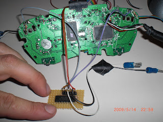
tried yesterday evening the inverter solution. Worked like a charm
Bye,
Jochen
and here some pics and yet another schematic
I’ve got a dual PS2/360 set-up with an inverted trigger MadCatz PCB (NPN method) and I tried this, but it doesn’t quite work for me. With the diodes in-place on the trigger signal line, the PS2 side works fine. However, the diodes (somewhat unreliably) cause problems with the 360 side - the triggers respond fine on their own, but they will not register if other buttons are being pressed - in other words, LT works fine alone, and RT works fine alone, but RT + A or whatever will not register the trigger inputs (For some reason, though, this isn’t always the case - sometimes the diodes are in and the 360 works just fine. I have no idea why it behaves some times and not others; nothing is shorting anything out as far as I can tell.) If I short out the diode, the 360 will work fine again (though of course the PS2 side will report the triggers as always active.) I wonder if maybe this is from the extra resistance added by the diode on the trigger line causing the signal to seek a different, lower-resistance route.
In any case, I think I am going to try and switch over to the inverter chip method, since people seem to be having no problems using that in dual-mod set-ups.
Thanks for the diagram trabus. I hate to sound like a broken record but…I have inverter chips on the way. The diagram makes sense except for one thing. I’ll be using this mod with a PS3 Cthulhu. It looks like the ground is contained to the chip only. How to I tie it in with the CG (located @ UP) to run it to the Cthulhu?
:wasted: OMG, I realize how stupid of a question that was as soon as I hit submit. The CG is already there (taken care of by the inverter). I just need to run each signal line to the appropriate point on the Cthulhu, correct? DUUUUUUUHHHH.
If you’ve already taken off the pots, could you use resistors instead? with a 2008-2009 madcatz pad
One thing that I’m going to try shortly for my dual-mod:
using 1 optocoupler per input (PC817 for instance) for complete isolation of the 2 pcbs (including triggers). The nice bonus is that you don’t have to use any inverter or transistor to connect a trigger to a digital input (or even connect a high active trigger to a low active digital input). That’s how I see things anyway. I just need time to experiment and verify if that idea translates well in practice.
See bencao’s thread for some schematics (connecting Sanwa/Seimitsu to non common ground pcb).
Wow this could save me alot of time. Thanks. :tup:
Why? 
If you’re having a problem with you’re stick/need a new one buy mine!
I’m selling HRAP ex for 150 + shipping. PM me for details.
Because it’s locking a pot in place. No problem if you’re not using the triggers, but if you want the triggers connected to buttons, it can.
Pot’s work as voltage dividers. If the pot is turned all of the way one way, so that the voltage on the wiper is all of the way high, then the resistance from the wiper to GND will be high, say 9.99k ohm, and the resistance from the wiper to the high voltage will be low, like 10 ohm.
Then you wire your button up between the wiper pin and ground like normal. As soon as you press that button, you are directly connecting the wiper pin to ground; there will be a connection between high and low of 10 ohms. The high voltages on these are usually either 5v or 3.3v. If its 3.3v, then there will be (I=V/R => I = 3.3/10 => I=330 mA) 330 mA of current wasted and going through the potentiometer. That’s high enough that the USB host can decide to kick the device off and shut it down, and it’s guaranteed to do that if two triggers are pressed this way.
Erm, but certainly, noone in their right mind would do what you describe, Toodles ?
Most posts in this thread say that a 10K resistor must be put between +5V and wiper, so those still using the pot would at least make sure they follow this guideline. If those people have no clue what they’re doing and worse, don’t care about what people here say is safe, then that’s their business, right ?
Which they can’t do if the pot is still on the board. Resistance goes down when resistors are in parallel. If the pot is turned so the wiper defaults to high, then the resistance from high to wiper is low, like I described above. They can put the 10k resistor between high and wiper if they like, but that would actually make things WORSE; the effective resistance between wiper and high would drop to something like 9.9 ohms.
Of course. I was asked ‘why?’ though, so was trying to explain why its a bad idea. I try to avoid the ‘Do what I say; I know what I’m talking about.’ card as much as possible.
The list of different ways to do I that I put up is still accurate. If folks dont want to follow it, it’s their call.
I meant use the pot as as resistor: cut one leg and turn the pot to get 10K resistance between the other two. I don’t think that applies to what you said in your post. That’s what I thought anyway (I read your post like “don’t use the pot AT ALL”).
Yes, I had noticed  And you’re also quick to acknowledge your own mistakes (something rare nowadays).
This and the fact that you have the will and talent to develop all sorts of funky gadgets for geeks is very much appreciated 
Okay, I have the inverters and have one wired up per Toodles diagram. The triggers are registering in windows. However, I’m also getting 1/2 movement on both X/Y axis as well. I have the signal wires going to the Cthulhu (Pins 2 and 4 on the topmost tight pads). I’m testing off of the Cthulhu (4K and 4P). Any ideas? Many thanks in advance.
I have it working now:wgrin: I was pulling the VCC/Ground from the USB cable. I decided to move them over the the appropriate spot on the Lt’s high/low connection and voila. Everything works great now.
Why is it that the first one is always a pain, then all the others go smooooooth?
Hi,
I’ve setup up a eagle layout for the inverter mod. I’m going to produce a bunch of pcbs. If you’re interested leave me a pm.

Hi Guys
I have been going through this thread and it helped me alot. The question I have is do you also need the 2 10k resistors and npn transistor for the original xbox 360 controller wired/wireless to get the LT / RT working as normal buttons?
I see this thread is based on the madcatz board and don’t know if this applies to original controller as well.
I have found links to xbox-scene’s forum with the apparent help and diagrams but they are down at the moment.
Please if anyone can help this is the last info that I need to get to start my custom project.
ok, i’m about to do a dual pcb hack with a madcatz retro stick pcb and MC Cthulu, i have just purchased 10k resistors from radioshack (10k-Ohm 1/2 watt 5pk for .99 cents), i want to be able to use the triggers on my new stick for the 360, do i need to get a diode as well or am i good to go?
EDIT
NVM, i went over the entire thread again, and found some of the pics and stuff that i overlooked, according to everything i’ve read what i bought is all i need, i just need to take off the pot switches and i’m good to go, thanx everybody