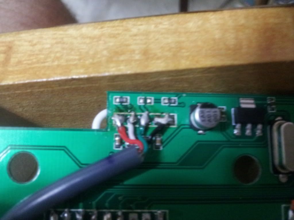
Here is a pic of what i am talking about, just to cleat all misscomunication ^^
and this is what i have so far:
It would make sense to me that this setup would work since this pcb is common ground, however my pc and xbox will not detect the pcb at all. What am i doing wrong?
EDIT: The order of the wires seems to be correct, but what would happen if i had the white and green wires in the wrong spots?
radio shack has connecters that fit these, the u,d,l,r
some one said theirs isnot reading on their x box, make sure your turbo button is wired right, unplug it from the system, hold down turbo, and plug in while holding turbo.
I’m wiring up a stickless controller using the Paewang, and I remember reading in another thread (the stickless one) that the red USB wire** isn’t** the VCC for the board – it’s the black (one? both?). Can anyone confirm / deny?
Fantastic. Thanks. That’s the only hard-wired connection I need to make to the PCB (I used terminals for the SOCD and the connections to the buttons) and I didn’t want to potentially fry the board.