U need a standalone app that will give users a visual interface to select default options prior to USB update (if possible). Checkboxes, radio buttons, drop down menus… select your options, then click the button to update firmware via USB… 
Yeah, we thought about that. But it’s some amount of work and atm there are not those many configuration options. We’d had to implement a HID device similar to the bootloader, that receives data from the PC and updates the EEPROM with it. An application to send this data from the PC to the Dual Strike is also needed. The next thing is the configuration GUI.
I plan to extend the bootloader to receive EEPROM data as the AVR GCC creates for the next Dual Strike, this code could be reused for the DSV1 firmware to be used in the configuration mode.
If I could do only interesting things… <dream>
Jep, I thought about this. We should make it happen 
I rather have auto detect than the pc config app.
The thing with auto-detect is that a USB device doesn’t get information about the host.
As I understand the UPCB code it checks for a non-standard request sequence to decide if it is a PS3. I rebuilt it with the V-USB framework we’re using, but it didn’t work. I came up with two possible causes: either V-USB swallows the non-standard requests or the UPCB itself is causing the non-standard behavior on PS3 by its USB implementation. Either way it doesn’t work for the Dual Strike. Another problem with this approach is that any time Sony could change its USB host implementation.
I don’t know if the Chimp does the auto-detection this way, but I suppose so…
Maybe if you ask nicely, he will tell you. LOL
Someone was telling me the autodetect performance on Chimp was inconsistent?
There are functions build into USB open source code that I was brushing up on to try and figure out how auto-detection could be possible. One of the specific functions is basically a “Query information from host,” allowing you to receive information from said host. If the host spits back “Unknown USB device (in some error code),” you know to hand over control to the 360 side. I think I came across the functions browsing the LUFA code, but I’m sure there are functions built into V-USB that allow for querying the host.

I don’t think it’s really “inconsistent,” but it’s the nature of screwing with the data transmission that causes weird shit to happen on the 360 side of things. There’s so many things that happen on start up for the 360 controller that when the USB transmission is messed with, it receives wrong data, which causes the random lights to occur that people see with ChImp boards. Usually it only causes Turbo and Guide lights to turn on, sometimes it doesn’t happen, sometimes it does. It only happens on the PS3 side of things though.
Again, I’ve only done a little bit of research into the open source USB framework stuff, but it was something that came across during research. I bought an Atmel ISP programmer and everything to delve into all of that shit…then I started the TEasy instead because I despise programming (even though I’m a little better at it than hardware design)
Never came across that, the only thing in this direction in V-USB is to receive data from the host. Do you have a name or something to feed into Google? The problem is that our PS3 mode works flawlessly on PC, so an error code wouldn’t be received.
Mephisto, for when you get to working on Wii, biggest bugs I’ve found so far with the original code can be recreated like so. I won’t discuss how I fixed them naturally, but you should definitely see them and fix them before widely releasing:
- Plug in during Wii main menu, test everything as fine, enter a game (VC or disc), and it spazzes. Ditto for plugging in during a game and then exiting to the main menu.
- NES VC titles will frequently not see the peripheral. Seems to happen about 1 in every 2 times the game is started from the Wii menu, especially when the game was in progress (start game, play game, home button, exit to Wii menu saves the state of the game. Going back in goes back to that saved state, and is when the peripheral isn’t seen.)
To the best of my knowledge, the only times it’s been inconsistent have all been fixed with a better quality 4066 chip. The LVP version I’m planning on using for the surface mount version coming soon should see that go away entirely due to an obscenely low ‘on’ resistance.
Very helpful! Thanks!
Nice to hear! I was interested in buying the TEasy PCB mod + Dual Strike to mod my 360 TE with, but having to either splice the stock USB cable or modify the cable compartment and replace the USB cable with a new one was what gave me second thoughts about going through with this project.
Good stuff Benaco and Phreak. I can’t wait to get my hands on these pcbs you guys are making. :tup:
Got some Dual Strike SMD updates.
- I restocked some more atmega8 chips to complete 50 boards. I can sell some if people are interested. Should note that it doesn’t have the ribbon connector like Ben’s version has so don’t plan on using the smd version with the TEasy.
-I figured out how to make the 360 analog stick work as digital inputs on the dual strike board. Meaning I could put the dual strike smd board in a MS 360 or madcatz 360 pad and have the left analog stick work on both 360 (remain analog) and ps3 (act as digital inputs). Don’t really know if anyone would be interested in a dual modded 360 pad, but its now completely possible
Thank you very much for the tips, but I didn’t even get it to work in the Wii menu. Meanwhile I recreated the Drum example of the Wii extension library, but I couldn’t get it to work either (the joystick movements and button presses don’t make a difference in the menu). I suppose the calibration data is incorrect at least for the classic controller. I don’t see why the Drum example shouldn’t work, except a GH drum has no functionality in the Wii menu (the guitars have).
I checked the transmitted data and there is communication going on with changing data being read on the same address, but I can’t really make anything out of it as of course it’s encrypted. I don’t have any idea what is going wrong, so I suppose there won’t be any competition for your PiiWee soon (congrats by the way for the ingenious name) 
Hey ben, found an easier location for the Dual Strike SMD board to be placed. Also, did you wire up the LS/DP/RS to the dual strike? I was only able to get the LS/DP functionality to work with the dual strike. I guess the TE/SE’s switch is a bit different than its fightpads.
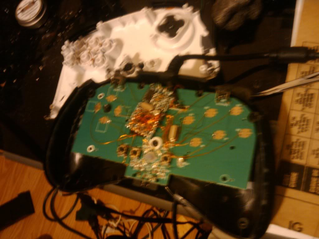
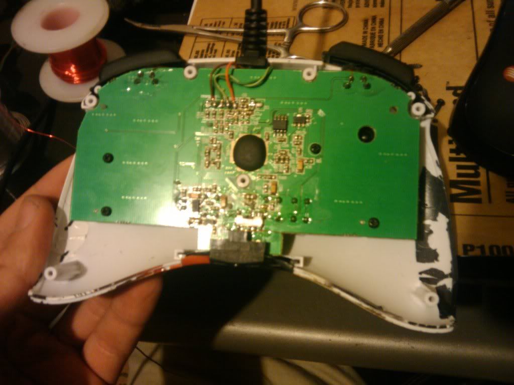
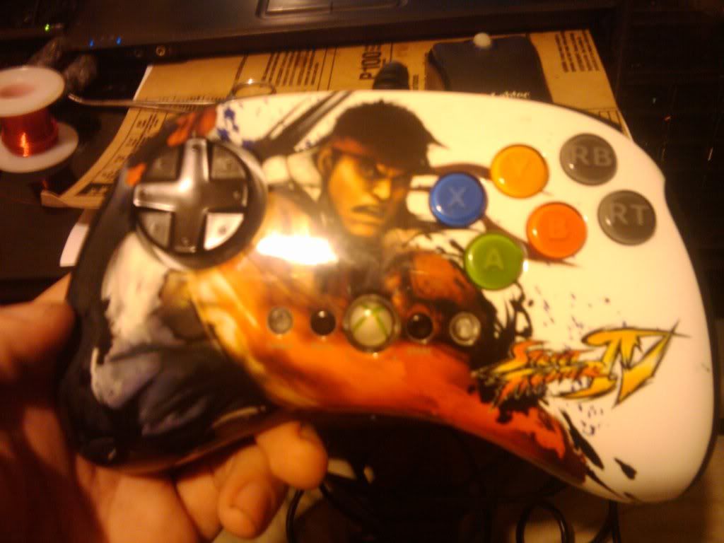
http://i79.photobucket.com/albums/j138/gocontourgo/Finished%20Mods/th_2010-06-08223602.jpghttp://i79.photobucket.com/albums/j138/gocontourgo/Finished%20Mods/th_2010-06-08223911.jpghttp://i79.photobucket.com/albums/j138/gocontourgo/Finished%20Mods/th_2010-06-08224921.jpg
I’m also thinking about redesigning the SMD boards to fit screw terminals for all the buttons and usb wires so it would be able to be used in conjuncture with the TEasy for a completely solderless mod.
whoa cool mod, but i have a mc cthulu, could i do it on that too? what are the contacts for each of the LEDs? im guessing ground and…?
what did you do to calculate resistence for the LEDs if you had to?
If you are using a imp board in your mod then yes you could. I don’t know which pins you would have to connect to on the imp board off the top of my head.
You would actually have the anodes both wired to the 5v source and have the cathodes wired to the imp.
Google “led resistor calc” to help you find the correct resistor value.
Great mod. Ive done so far 2 dual mods with fight pads. The imp like functions works in your mod, nor? But no, I didn't used the switch functionality (I wasn't aware that they can set in a fightpad to be honest). The Dual modded Fight Pads works like a charm.. :) I see that youre using copper wire. Are they good to handle?
The upcoming prototype of my re-design has screw terminals for all signals :
- Signals for switching the 4066. So you can make IvlePhisto LED Mod soderless. This signals specify which console is currently connected. So you can do other fancy stuff with this lines
- Signals for DP, RS, LS. Tough, they`re configurable (inverted trigger i.e.), nothing new here. They was accessible in the old version, too.
- USB Datalines are accessible via screw terminals now. So this big bad USB B Plug is not needed anymore to make a TE mod or something similar
- Some more GND ScrewTerm to simplify wiring
- 4 symetrical mounting holes
- SMD parts for diodes, resistors, capacitors and 4066
- Elko, Clock, MCU is THT
I`ve ordered again the old version to have a complete THT version. THT means Through Hole Technique. This one is very easy to assemble and solder yourself. This way Dual Strike can be still offered as kit.
So we`re open for further FW update.
I like this!! I`ve to order some of this PCB in near future.
Wow, great news bencao! Looking forward to getting my hands on one of these. Well done and keep it up!
ah yeah im gonna be using an mc cthulu and madcatz fightpad for 360 for a dual mod and DPDT switch.
oh so for each LED its the 5v thats connected to either pcb? and for each LED it would be connected to either the 360 pcb ground or the cthulu pcb ground? thats for the help gummowned!
mm, you have it wrong. If you aren’t using the imp board and you are using a physical switch, you would have to have the leds wired to the switch. But since you are using a DPDT switch you wont have any extra poles on the switch to handle the switching of the leds.